

Pre-Assembly Preparation and Workspace Zone Planning
Assembling an adjustable workstation requires thoughtful site preparation and methodical staging. Before opening packaging or loosening hardware bags, setting aside an expansive staging zone ensures that structural components remain unblemished and ready for accurate mechanical alignment.
Unboxing, Hardware Inventory, and Surface Protection
Begin by organizing all structural members, fastening hardware, and electronic components. Unpack the desktop, lifting columns, crossbeam rails, foot assemblies, support brackets, control box, handset, and power cables onto a soft, protective surface. A clean area rug, moving blanket, or the flattened shipping carton provides an ideal buffer that prevents cosmetic marring on polished or veneered tabletop finishes. Carefully separate bolts, washers, wood screws, and hex keys into dedicated groups. Verifying that each piece of fastening hardware matches the component checklist prevents interruptions midway through the mechanical build.
Spatial Clearance and Inverted Build Area Requirements
Most motorized frames assemble upside down, requiring sufficient open floor area to rotate the finished workstation into an upright orientation without striking adjacent walls or nearby shelving. When laying out your assembly area, coordinating your floor plan with an ergonomic workstation planning guide ensures sufficient perimeter clearance once upright. Plan for a generous perimeter around the build mat so two people can comfortably position themselves on either side of the table during final inversion.
Frame Architecture and Mechanical Assembly Workflow
The structural integrity of an adjustable workstation relies on balanced fastening, square framing, and precise physical alignment across the entire undercarriage.
Lifting Column Orientation and Side Bracket Attachment
Position the primary motorized lifting columns parallel to one another on your staging surface. Fasten the steel side brackets to the top plates of the lifting columns using the designated machine screws. Tighten the hardware evenly in an alternating diagonal pattern to seat the bracket completely flush against the column housing. Uneven torque at this junction can introduce slight structural angling, which compromises smooth vertical gliding during motorized operation.
Telescopic Crossbeam Sizing and Center Transmission Rod Alignment
Users assembling a wide adjustable standing desk frame must verify that crossbeam extensions remain symmetrical along the center support beam. Loosen the crossbeam expansion bolts to extend the inner rails until the total width aligns with the mounting holes on the underside of your desktop. Maintain equal extension on both the left and right sides of the central rail assembly to preserve the center of gravity. For single-motor models equipped with a synchronized drive axle, slide the hexagonal transmission rod through the motor gearbox and into the opposing leg receptor. Ensure the hex rod is inserted fully into both ends before locking the central collar set screws firmly in place.
Desktop Surface Fastening and Pre-Drilled Hole Registration
Align the fully framed undercarriage over the inverted tabletop surface, matching the bracket slots with the factory-drilled pilot holes. If your model includes rubber dampening washers, place them between the steel frame and the wooden desktop to reduce mechanical vibration resonance during elevation changes. Drive the wood screws into the pilot holes using a manual screwdriver or a low-torque drill setting to avoid stripping the timber substrate. Ensure the frame sits equidistant from both tabletop side edges for optimal stability.
Electrical System Integration and Keypad Setup
Proper electrical connections and initial controller synchronization establish smooth, dependable height adjustments across daily work routines.
Motor Wiring, Control Box Mounting, and Handset Connection
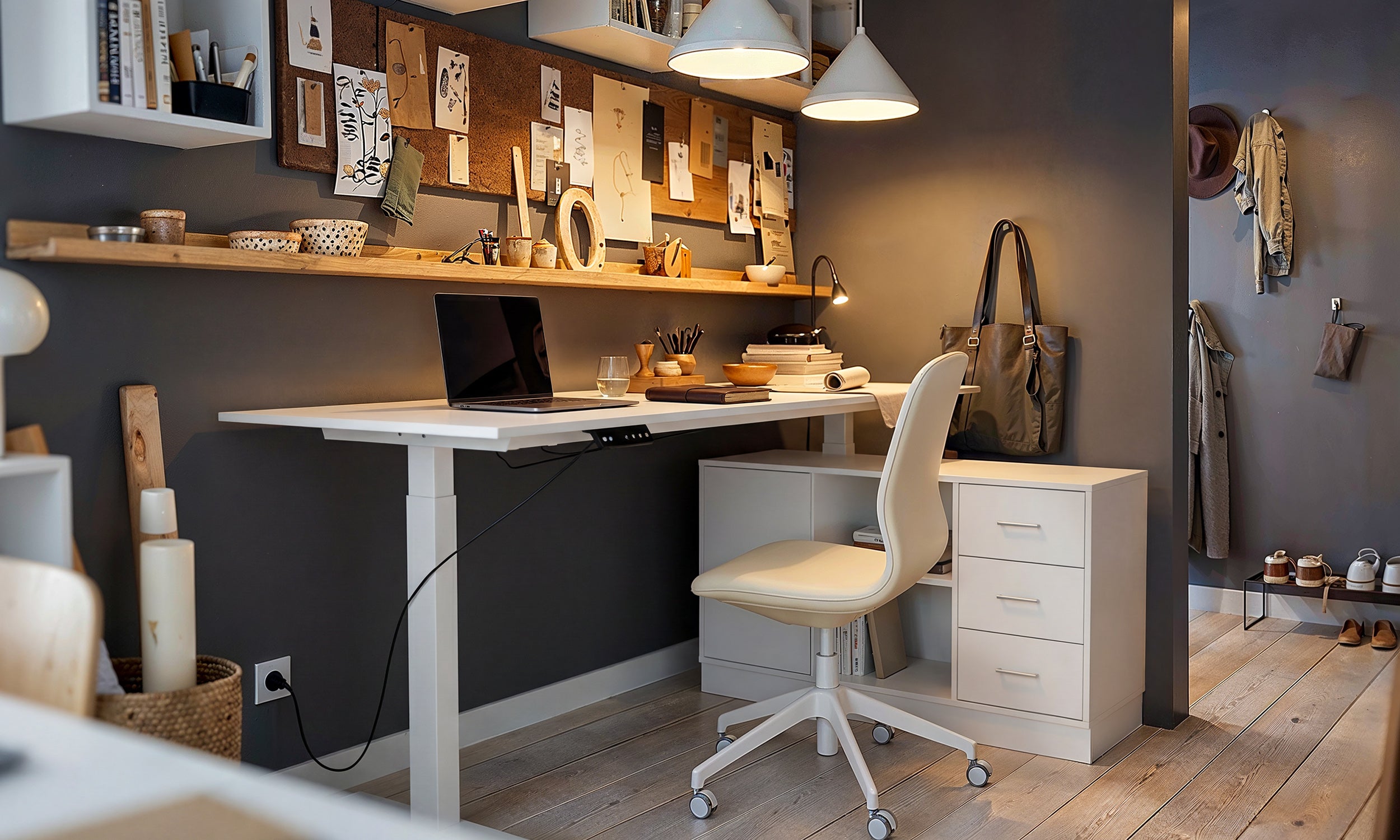
Secure the central electronic control box to the underside of the desktop near the motor access channels. Connect the primary motor cables firmly into their assigned ports until the locking clips click into position. Insert the digital handset cord and the main power supply lead into the corresponding module sockets. Configuring a motorized standing desk with memory presets requires setting comfortable sitting and standing elevations during initial calibration, making accessible keypad placement essential for everyday convenience.
Initial Reset Procedures and Height Memory Calibration
Once the desk is rotated upright and connected to a reliable wall outlet, the electronic control module must complete a synchronization cycle before standard operation begins:
- Press and hold the down button on the handset until the lifting columns travel to their absolute lowest mechanical stop.
- Continue holding the down button until the digital display flashes or the system emits an audible chime, indicating the baseline height has been calibrated.
- Release the button, then raise the desk slightly to verify uniform, level ascent across both telescoping legs.
- Program personal ergonomic sitting and standing positions by elevating the surface to the preferred height, pressing the memory key, and assigning the corresponding numeric preset.
Diagnostic Error Code Framework and Mechanical Leveling
If the handset displays an error or pauses mid-travel, it often indicates an uneven leg baseline, loose cable connection, or triggered anti-collision sensitivity. In the event of unexpected travel stoppage, confirm that all motor connection plugs are seated securely within the control box. Repeating the foundational downward reset sequence resolves most electronic calibration variances and restores synchronized travel across dual-motor systems.
Dynamic Cable Management and Articulation Slack
A motorized workstation moves through a continuous vertical arc, requiring dynamic cable pathways that protect electronic cords from tension strain or entanglement.
Under-Desk Cable Tray and Power Strip Anchoring
Fasten a rigid horizontal wire raceway or mesh cable hammock to the undercarriage near the rear edge of the desktop. Mount a multi-outlet surge protector directly inside the tray to act as a centralized power hub for monitors, laptops, task lamps, and auxiliary peripherals. Grouping transformer bricks and power adapters within an under-desk channel prevents unsightly hanging bundles and keeps floor zones completely clear for natural foot movement.
Vertical Articulation Routing and Strain Relief
Integrating wire raceways according to designer standing desk layout concepts keeps open-plan offices visually uncluttered. Route all peripheral cables into the centralized under-desk tray, leaving only a single main power supply cord descending to the wall outlet. When routing this primary drop cable, raise the workstation to its highest vertical elevation and provide sufficient slack along the travel path before securing the cord to the desk leg with adhesive clips or an articulating cable spine. This slack loop prevents accidental disconnections and mechanical stress during full elevation extension.
Spatial Footprints, Storage Synergy, and Stability Maintenance
Creating an organized, wobble-free work zone involves pairing adjustable surfaces with compatible decoupled storage units and maintaining structural hardware over time.
Decoupled Storage Pairing and Clearance Boundaries
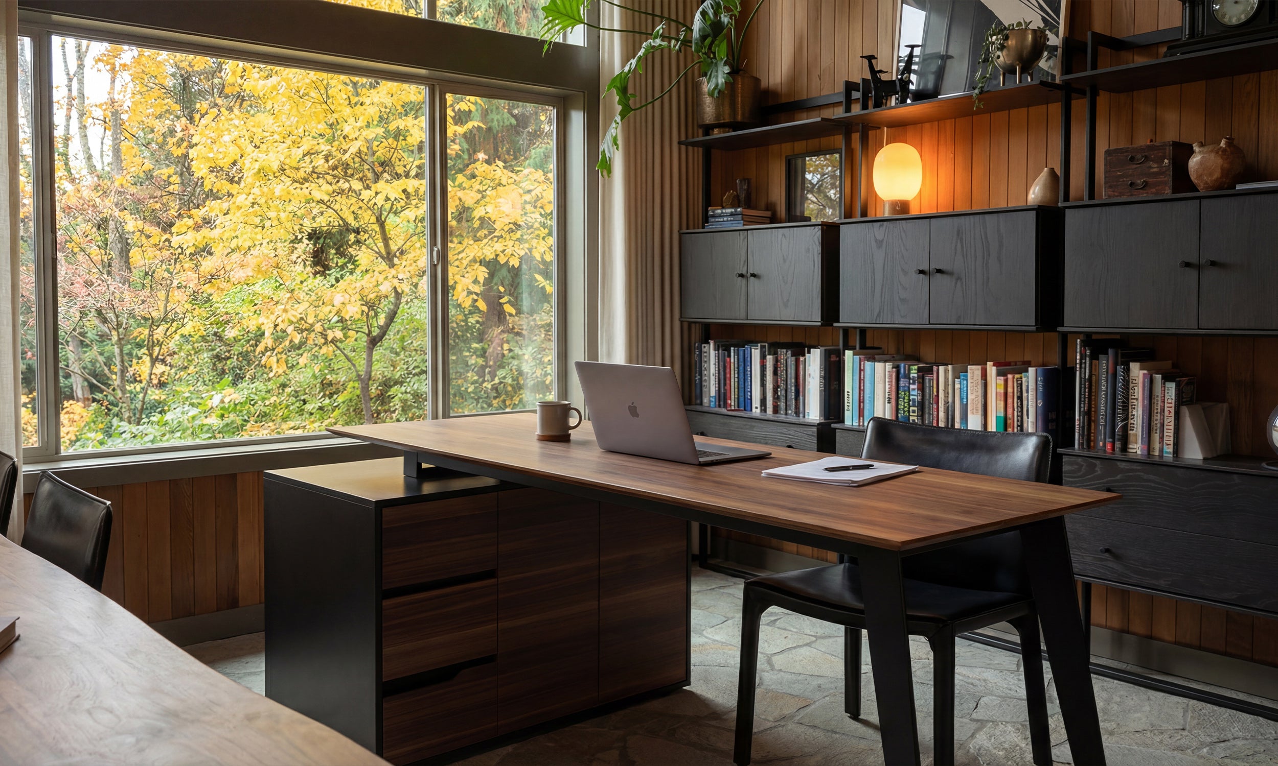
Because the primary surface moves vertically, under-desk storage elements must remain completely decoupled from the lifting mechanism. When pairing mobile file cabinets beneath a large format electric standing desk, ensure vertical travel zones are completely unobstructed. Maintain a safe vertical gap between the top surface of low-profile rolling pedestals and the lowest travel limit of the desk crossbeams to eliminate collision risks during downward adjustments.
Leveling Foot Adjustment and Periodic Hardware Fastener Maintenance
Even minor floor irregularities can cause lateral sway when a desk is extended into elevated standing configurations. Rotate the adjustable threaded glides on the base of each foot until the desk rests completely level in all directions without rocking. Establish a routine seasonal maintenance schedule to inspect structural connections. Retighten crossbeam expansion bolts, side bracket fasteners, and transmission rod set screws to preserve rigid mechanical stability and silent lifting performance throughout the lifespan of your workstation.


Laisser un commentaire
Ce site est protégé par hCaptcha, et la Politique de confidentialité et les Conditions de service de hCaptcha s’appliquent.