

Kinetic Lift Architecture: How an Adjustable Desk Mechanism Operates
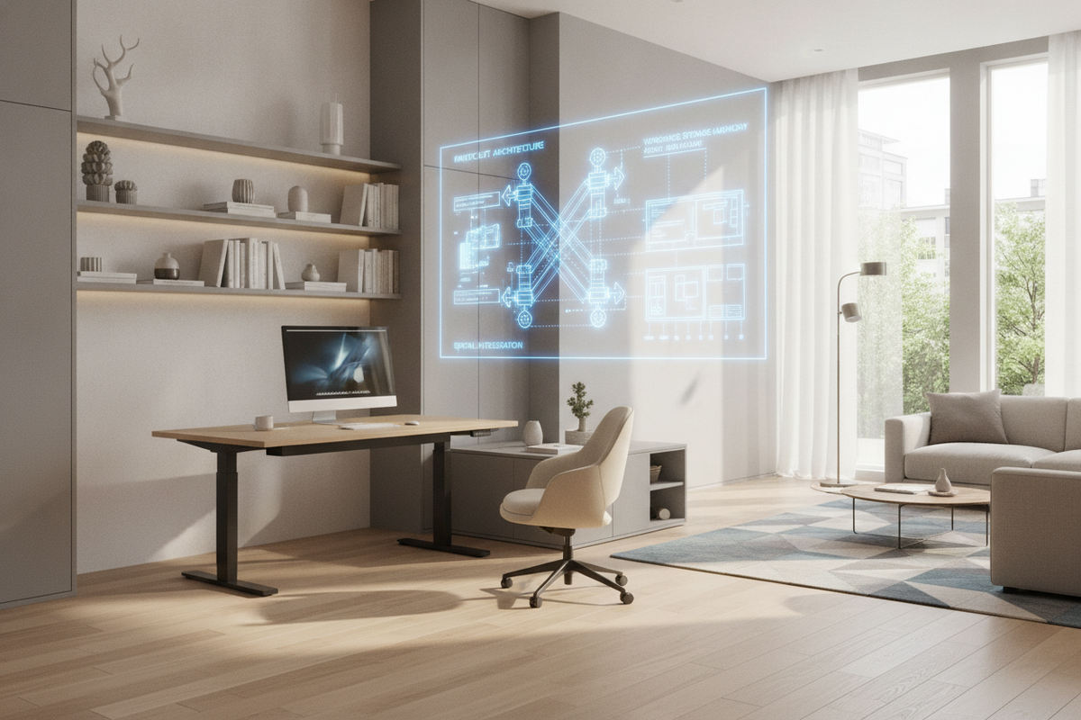
Modern height-variable workstations rely on integrated linear engineering to transition smoothly between seated and standing elevations. At the foundation of every kinetic workspace is the adjustable desk mechanism, a structural assembly designed to distribute mechanical force evenly across vertical support columns. Understanding how these mechanical components interact allows interior planners and home office builders to select frames that maintain rigidity, minimize mechanical wear, and preserve alignment across years of continuous elevation shifts.
Telescoping Columns and Stage Geometries
Vertical lifting columns consist of nested steel profiles known as stages. Workstations typically incorporate either two-stage or three-stage telescoping legs. In a two-stage column, one inner sleeve travels within an outer base tube, offering a standard height range suitable for users with average seated and standing requirements. A three-stage column introduces an intermediate nested tube, expanding both the minimum low point and maximum top reach to accommodate a broader ergonomic spectrum.
Between these metal stages, internal glide shims—often fabricated from low-friction composite polymers—facilitate linear travel. These shims prevent direct steel-on-steel friction, absorb micro-vibrations, and establish structural preload. Adequate overlap between stages at peak elevation remains critical; greater stage overlap prevents lateral play and eliminates noticeable monitor sway during typing tasks.
Lead Screws, Worm Gears, and Linear Actuators
Rotary power generated by internal motors converts into linear vertical movement through a precision lead screw or ball spindle encased within each column. As the motor turns, a reduction gearbox—frequently using worm gear geometry—steps down rotational velocity to amplify mechanical torque. The rotating threaded spindle drives an internal traveling nut upward or downward, extending or retracting the nested column tubes in unison.
Drive Mechanism Tiers: Manual, Pneumatic, and Electric Desk Lift Mechanisms
Lifting mechanisms vary significantly in their mechanical propulsion, operational cadence, and structural configuration. Selecting the appropriate propulsion method depends on power access, payload requirements, and intended workflow flexibility.
Electric Desk Lift Mechanism: Single vs. Dual Motor Systems
The electric desk lift mechanism represents the primary standard for modern workstations due to programmable control interfaces and consistent lifting speeds. These systems typically fall into single-motor or dual-motor architectures:
- Single-Motor Systems: Utilize a solitary drive unit mounted under the desktop or within one leg, transferring mechanical rotation to the opposite column via an exposed or enclosed hexagonal synchronization rod. While cost-effective, single-motor systems often exhibit lower payload capacities and require precise initial alignment to prevent drive rod binding.
- Dual-Motor Systems: House dedicated, synchronized motors within each column housing. An electronic control box coordinates motor rotation, ensuring parallel travel across both sides. Pre-engineered solutions like an adjustable height standing desk with electric lift system leverage synchronized dual columns and digital memory presets to maintain balance even under asymmetrical surface loads.
Non-Electric Alternatives: Manual Cranks and Pneumatic Gas Struts
Where electrical outlets are inaccessible or mobile flexibility is paramount, manual and pneumatic lift systems provide capable alternatives. Manual crank desks utilize bevel gear assemblies and telescoping drive shafts turned by a stowable hand crank. While mechanically dependable and free of electrical requirements, manual elevation adjustments require physical effort that can discourage frequent posture changes.
Pneumatic workstations employ pressurized gas struts counterbalanced to lift moderate surface weights with the release of a hand lever. These mechanisms excel in lightweight, mobile setups but require careful load matching; overloading a pneumatic surface hinders upward travel, whereas underloading can cause rapid upward extension when released.
Structural Load Capacities and Frame Stability Frameworks
A reliable desk lift system must balance dynamic mechanical performance with stationary structural rigidity. Selecting an appropriate frame demands an evaluation of both active lifting power and structural anti-racking design.
Static vs. Dynamic Lifting Dynamics
Workstation load ratings fall into two distinct engineering categories: dynamic capacity and static capacity. Dynamic capacity represents the maximum balanced weight the motor drive system can lift while in active motion without overheating or straining internal gears. Static capacity defines the resting payload the stationary frame, columns, and floor glides can structurally support once elevation stops.
Calculating desktop payload involves factoring in the weight of the solid wood, laminate, or composite desktop itself, combined with monitor arms, computing hardware, task lighting, and under-desk cable management trays. Operating well within dynamic payload parameters preserves motor longevity and maintains consistent linear velocity.
Crossbar Architecture and Lateral Anti-Racking Design
At elevated standing heights, desks become susceptible to lateral sway and front-to-back rocking. Mechanical stability is determined by structural connection geometry:
- Telescoping Crossbeams: Structural steel rails connecting the tops of both lifting columns resist frame racking and distribute desktop weight across the chassis.
- Cantilevered Top Brackets: Deep desktop mounting plates prevent longitudinal bowing across broad solid wood or composite surfaces.
- Column Orientation: Standard upright columns position the widest nested tube at the bottom floor plate, whereas inverted columns position the widest tube directly beneath the desktop to optimize resistance against upper-chassis leverage forces.
- Foot Plate Geometry: Elongated, heavy-gauge steel base feet lower the workstation center of gravity and provide adjustable leveling glides to compensate for irregular subfloors.
Spatial Clearance, Wall Offsets, and Kinetic Cable Management
Because an adjustable desk moves through a dynamic vertical envelope, room planning requires proactive spatial allowances to prevent structural collisions and component strain.
Vertical Travel Zones and Perimeter Clearances
Kinetic workstations must never be placed flush against architectural boundaries. As a desk ascends and descends, minor mechanical deflections or uneven wall surfaces can cause friction, scuffing, or motor stalls. Reviewing practical layout planning considerations for adjustable workstations helps prevent positioning errors near window sills, electrical conduit, or adjacent fixed furniture.
Maintaining an intentional perimeter buffer around the entire desktop edge safeguards equipment, eliminates finger pinch points, and prevents collisions with low-hanging task shelves or wall trim.
Kinetic Cable Spines and Power Distribution
Standard static cable routing fails on height-variable desks. As the surface travels upward, cables connecting stationary wall outlets to moving monitors and computer towers experience direct tensile strain. Effective kinetic management relies on articulated cable vertebrae or flexible mesh raceways mounted to the under-surface crossbeam. These routing tracks flex predictably along a controlled vertical spine, maintaining gentle bend radiuses and ensuring power and display leads never stretch or snag during transitions.
Workspace Storage Architecture and Decoupled Modular Organization
Integrating meaningful storage alongside a height adjustable desk mechanism requires a balance between mobile, suspended, and stationary modular elements.
Integrated Desktop Organizers vs. Independent Base Storage
Storage integration generally follows two distinct structural approaches: onboard kinetic storage and decoupled static storage. Onboard solutions, such as slim under-mount drawers or a modern electric height adjustable desk with integrated organization, lift alongside the primary surface. This architecture ensures essential stationery, charging hubs, and daily tools remain immediately accessible across both seated and standing postures without altering reach geometry.
Conversely, heavier storage elements—such as multi-drawer filing pedestals and computer tower cradles—are often best deployed as independent mobile units resting on castors beneath or beside the frame. Decoupling dense storage preserves the mechanism dynamic payload capacity and prevents structural binding.
Perimeter Wall Storage and Modular Shelving Harmony
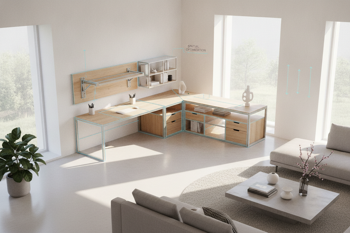
To maximize vertical room utility without intruding on kinetic travel envelopes, surround the desk with independent perimeter cabinetry and adjustable modular shelving systems. Installing adjustable wall shelving above the standing envelope provides generous storage for reference materials, media, and display objects while keeping the desk kinetic path completely clear.
Aesthetic Cohesion Across Active and Static Elements
Creating an architecturally cohesive workspace involves harmonizing the industrial steel finishes of kinetic desk frames with adjacent wooden casework, credenzas, and acoustic panels. Drawing inspiration from strategies for styling adjustable furniture for an elevated aesthetic allows designers to unify powder-coated metal legs, natural desktop grains, and perimeter storage into an intentional, clutter-free professional environment.
Mechanical Calibration, Assembly Architecture, and Long-Term Maintenance
Achieving silent, level, and durable vertical travel depends on meticulous initial assembly and periodic drive calibration.
Precision Frame Squaring and Fastener Torque Sequencing
During initial assembly, lifting columns must be strictly squared relative to the structural crossbeams and the desktop underside. Tightening frame fasteners out of sequence can introduce subtle chassis twists that cause telescoping columns to bind under load. Follow a progressive cross-torque tightening sequence, fastening bolts loosely until the full frame is positioned, checking diagonal measurements across mounting brackets, and then securing all hardware to equal tension.
Spindle Synchronization and Control Module Reset Routines
In multi-motor lift systems, electronic control boxes periodically require baseline calibration to ensure both lifting columns operate at identical heights. If a column experiences uneven resistance or an unexpected power interruption, the internal pulse counter may register a minor height offset.
Executing a standard control module reset—typically performed by driving the desk to its lowest mechanical limit and holding the down button until the system beeps or recalibrates—re-indexes the zero baseline for both columns. Ensuring that anti-collision sensitivity thresholds are correctly configured further protects the structural mechanism, peripheral furniture, and surrounding architectural finishes from accidental impact during everyday elevation shifts.

Laisser un commentaire
Ce site est protégé par hCaptcha, et la Politique de confidentialité et les Conditions de service de hCaptcha s’appliquent.